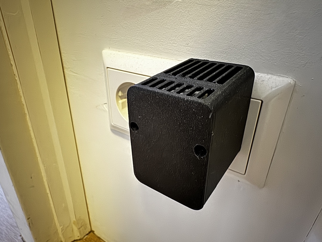
This past year I have become *completely* obsessed with HomeAssistant, adding a number of sensors and smart products all over our house all controlled through HomeAssistant (from the Everything Presence One mmWave sensor in my office to the Roborock vaccuum and even our solar system). However, due to the way our underfloor heating is setup, we have no thermostats and as such, no real way to monitor the temperature of our home. My wife was looking into buying a bunch of cheap battery powered LCD displays, but of course, that wasn’t happening on my watch!
So I started looking into building some smart sensors that we could use around the house to monitor temperature and humidity. There are lots of options using Zigbee and Z-wave, but they are mostly battery powered and I hate changing batteries (my ADHD brain will put it off for weeks). They also lack flexibility – they do what the manufacturer designed them to do and nothing more.
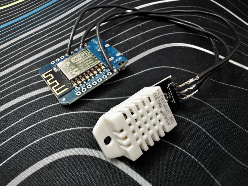
So with my wife’s approval, I started looking into cheap DIY solutions that can use ESPHome and sure enough, there are loads of solutions out there. Unfortunately, they all look something like this:

A small microcontroller, with a sensor hanging off, connected via USB to a wall-wart. These are fine if you can hide them away, but doesn’t work in all situations and has low wife approval factor (also when my wife sees things like this she gets stressed that I’m going to burn the house down). Of course, you can shove the whole lot in a project box or disguise it to look like an ornament but even that still requires running cables.
So I started thinking if it would be possible to build a wall wart with a built in ESP-type microcontroller and a small prototyping area for adding sensors and sure, with the right manufacturing partner, this is totally possible but I’m going through some stuff right now and didn’t want to be looking into big manufacturing runs and financial commitments just now. So… I did the next best thing.

I designed a slim, 3d printable enclosure that sits around a €2 USB phone charger that gives you a ton of flexibility to make your own plug-in ESPHome devices without breaking the bank and without looking looking too much like a DIY project!
Want to make one for yourself? Keep reading!
Parts list
The parts list is pretty simple, but also flexible – you can substitute most of the parts for similar alternatives depending on your own needs and budget. I wanted to build around 8 of these, I kept it cheap and cheerful (at the cost of presicion).

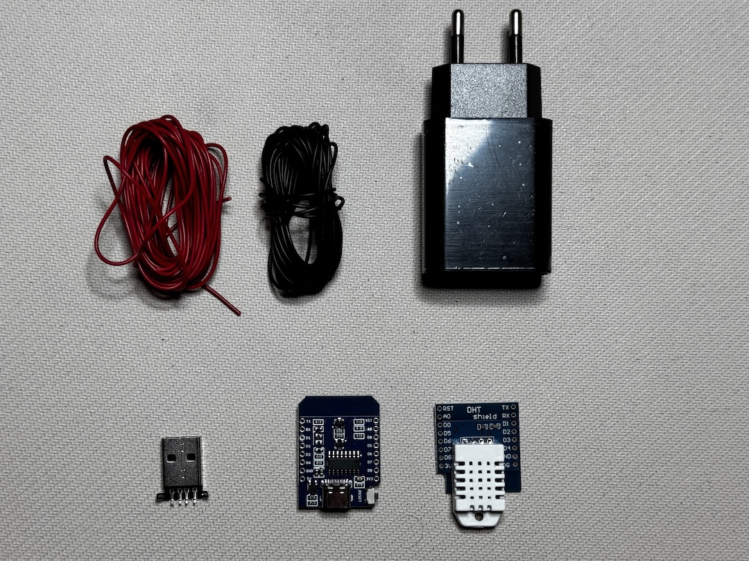
To build this project, you will need: (note there are no affiliate links below!)
- A Microcontroller. I have designed this to accept any D1 Mini format microcontroller. I used an ESP8266 D1 Mini, however you could use the ESP32 equivalent or even other form factors such as the Xiao boards from Seeed Studio. The D1 Mini boards usually come with a set of correctly sized male and female headers – you’ll need them too.
- A sensor. For my build, I’m using a DHT22 Temperature and Humidity sensor. It’s not perfect but it is cheap, and for added convenience, it comes in a “shield” form factor which makes it easy to plop ontop of the D1 Mini (and easy to exchange for other sensors if needed!).
- A Male USB 2.0 Header with the pins exposed. You can also get them with breakout boards but those are more expensive, bulkier and honestly overkill for this project.
- A 5V, 2A USB charger designed for mobile phones. This is a pretty standard form factor in the EU, but I can’t guarantee that other options out there will fit in my specific case design, so get this exact one if you can!
- 2 x M3 screws. I use the fancy hex head ones because that’s what I have. They need to be at least 10mm long but there is room for longer ones. If you don’t plan to take it apart again, you an always just glue the two parts together or weld them using a soldering iron.
- Some wire (doesn’t really matter, we’re not dealing with high voltage here). I prefer to use silicone coated flexible wire for flexibility.
- 3D Printed parts. You can download these from my Printables free of charge. I print these face down on the bed (as supplied) with no supports (technically you should probably support the screw holes on the front cover but my printer seems to cope just fine without). I crank up the number of perimeters to create a nice strong print without much infill. Material wise, PLA and PETG are plenty for this use. I suggest black and white if you want them to blend into your home and get maximum spouse approval factor!
- You will also need a soldering iron and some solder.
Note, if you order from Aliexpress, I suggest buying a couple of spares. The specific parts I recommend above worked fine for me, but I have had parts delivered dead on arrival in the past.
How to build:
If you use my exact parts, this is really straight forward (if not, you’re on your own!).
- Solder the male headers to your microcontroller. I find using a breadboard to hold everything in place makes this easier. Because I’m making a lot of these, I didn’t solder all the pins. Just the 5V, GND, 3V (and TX/RST for stability). I put the pins sticking out on the same side as the ESP module and the USB port on the outside
- Solder the female headers to your DHT22 shield (make sure the orientation matches such that the white sensor module is on the outside. To make this easier, I mount the female pins on the ESP module, drop on the sensor and then solder it in place (again, only soldering the needed pins).
- Trim your wires to length (40mm should be plenty), strip a couple of mm off the end, twist until tidy and tin the ends with solder.
- Tin the positive and ground pins on the usb plug (of the four central pins, these are the outside most pins). You won’t be transmitting data so you can always trim off the middle pins to make your life easier!).
- Solder the positive wire to the positive pin on the usb header (this is the right-most pin if you orient the connector as it is in the photo above). Solder the ground wire to the ground pin (it’s the one on the other side).
- Solder the other end of these wires onto the 5V and GND header pins on the ESP board (being careful not to touch any other components on the board).
- Check everything is secure.
At this point, I suggest plugging the usb connector into your usb charger and sticking it in the wall. The status light on your ESP device should blink briefly if you got everything correct. Unplug it from the wall and then connect it up to your computer using a data-capable usb cable.
ESPHome configuration
All that remains is to setup the device in ESPHome. I’m going to assume you have some basic knowledge here and give you the tldr. Provision the device using the ESPHome Web Flasher in a chromium based browser and connect it to your wifi. The name you give it doesn’t really matter that much.
Once you have done this, head to the ESPHome Compiler and click “add new device” in the bottom corner. Follow the instructions and your device should pop up in ESPHome.
Finally, click edit and copy/paste the code below beneath the line containing captive_portal: into your device configuration file then save and upload the code to your ESP device. That should be it – you should be able to see the “visit” button and see the logs and value after a minute or so (although I will say, I have noticed that the DHT sensor doesn’t’ report a value unless it’s plugged into the wall to get a proper 5V signal).
# To have a "next url" for improv serial
web_server:

# DHT22 Sensor configuration
sensor:
  - platform: dht
    id: dh222_sensor
    pin: GPIO2
    model: DHT22
    temperature:
      id: temperature_sensor
      name: "Temperature"
      unit_of_measurement: "°C"
      accuracy_decimals: 1
      filters:
        - offset: 0
        - lambda: "return x + id(temperature_offset_ui).state;"
    humidity:
      name: "Humidity"
      id: humidity_sensor
      unit_of_measurement: "%"
      accuracy_decimals: 1
      filters:
        - offset: 0
        - lambda: "return x + id(humidity_offset_ui).state;"
    update_interval: 20s

number:
  - platform: template
    name: "Temperature Offset"
    id: temperature_offset_ui
    unit_of_measurement: "°C"
    min_value: -20
    max_value: 20
    step: 0.1
    mode: box
    update_interval: never
    optimistic: true
    restore_value: true
    initial_value: 0
    icon: "mdi:thermometer"
    entity_category: config
    on_value:
      - lambda: 'id(dh222_sensor).update();'

  - platform: template
    name: "Humidity Offset"
    id: humidity_offset_ui
    unit_of_measurement: "%"
    min_value: -50
    max_value: 50
    step: 0.1
    mode: box
    update_interval: never
    optimistic: true
    restore_value: true
    initial_value: 0
    icon: "mdi:water-percent"
    entity_category: config
    on_value:
      - lambda: 'id(dh222_sensor).update();'
You will notice that there is an “offset” option for the temperature and humidity sensor – this allows you to adjust your sensor to compensate for their crappy accuracy and any heat that might be generated by the ESP module. Credit where it is due – I totally stole this from the Everything Presence One GitHub repo and modified it to work in this use case.
All that is left is to shove the enclosure over your 5V usb plug (note the plug is slightly tapered so it’ll only go in from one end and then press fit into place, although you can make it more secure with a bit of glue), connect the microcontroller and screw the case together, then add this to your HomeAssistant devices (it should be auto discovered in most circumstances) and use the data as you see fit!

Ignore the insane temperatures – my house is definitely not this hot
Other uses for this setup
I could have made this device quite a bit smaller but I like the idea of keeping things flexible so that it can be useful for more people. Here’s some ideas to get you started:
- mmWave sensor for presence detection
- setup a bluetooth proxy for mobile-based presence detection or use it as a bluetooth repeater for HomeAssistant
- add one or more rgb leds and use it as a visual notification indicator (even better if you print the cover in translucent material!) or as a nightlight (you can use WLED if you want to get super fancy!).
- Add more advanced gas sensors such as the BME680 to monitor air quality.
- Use an IR receiver to take commands from a remote and relay them to other devices in your smart home!
- Add a buzzer and use it as a doorbell chime!
- Chuck in an M5 stack atom echo and use it as a virtual assistant.
- Want more airflow or light to pass through? In your slicer, add a modifier shape to the front cover and set it to zero top and bottom layers, then use a sexy infill like honeycomb to create a hexagonal grid pattern in a selected area.
As you can see – there are many possibilities and you can even combine multiple sensors in the same enclosure to add more functionality if you so wish! I recommend if you want to add other sensors, consider picking up some D1 shield format perfboard to give you something to build on top of.
Closing words
Building this has been a fun project that has satisfied an urge that I’ve had for a while. I had seriously considered starting a Kickstarter for something more polished but there is nothing truly original in this project that couldn’t be cloned in five minutes by even the most basic of manufacturing facilities. If you don’t have a 3d printer or want a more polished end product, I suggest looking into professional 3d printing services from places like JLC PCB, who can take this to the next level for you.
Finally, if you make one of these – please share your make on Printables, this gives me points that I can use to redeem for more filament, which allows me to make more cool projects in the future.
Good luck and happy making!
I love the design, the ones I made were a lot cruder.
Do you have any pictures of how you placed everything in the case.
I see lots of options in placement but what did you use especially with the usb header.
Thank you
@carltonb it’s deliberately kept very open so you can use anything you like inside. The plug goes in the big hole and you pop the usb connector into the usb hole on the charger. The void in the top is for your microcontroller and sensors. If you check out the 3d model on printable it should be pretty obvious.